REINFORCING STEEL PLANNING
Site restrictions and intentions for the exposed concrete make it critical to plan in detail the ordering, fabrication, layout, and installation of the reinforcing steel. The excavation and concrete pour sequencing necessitates determining which assemblies will be fabricated off site and delivered ready for installation and which assemblies will have to be fabricated on site. It has to be determined which fabrications are to be installed using equipment and which will be installed manually. Detailed planning of the reinforcing steel layouts is essential to achieve the desired joints, concrete tie patterns, and location of various embedments in the exposed concrete.
Sequencing
The concrete sequencing determines the specific reinforcing steel to be installed for each sequence. Only the steel required for a single sequence is delivered to the site at one time because the area for material storage on site is limited. Often the concrete sequencing creates structural joints between pours necessitating bars in one pour anticipating subsequent pours. The sequencing is designed to the extent possible to minimize the significant extra steel required to make the structural overlaps.
Fabrication
Neighborhood and site characteristics along with the sequencing determine which steel reinforcing assemblies, such as pile cages and grade beam cages, are fabricated off site and delivered to the site ready for installation and which assemblies are to be fabricated on site. The neighborhood street conditions restrict the size of delivery trucks that can access the site and the site size and slope limitations help determine the maximum lengths of fabrication and steel pieces that can be delivered and unloaded at the site.
Individual steel fabricated pieces to be delivered loose and assembled on site are designed to minimize required structural overlaps, especially at grade beam intersections and wall corners.
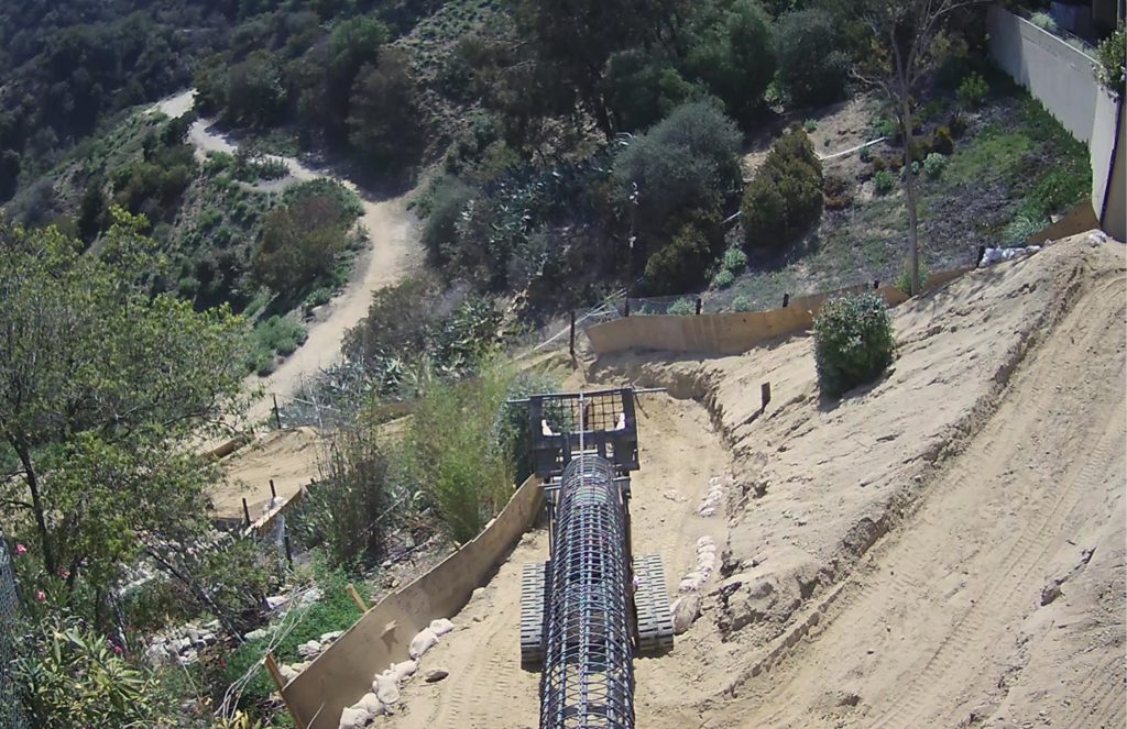
Delivery
These length and weight limitations cause many of the pile rebar cages to be delivered in two pieces and joined during installation. Many of the grade beams are too large to be delivered as assembled units and are thus assembled on site. The maximum lengths of the steel pieces to be delivered and assembled is determined by the 30- or 40-foot maximum length of flatbed trucks that can reach the site and the maximum weights determined by what can be maneuvered on site with manual labor.
The sequencing of the excavations and concrete pours and whether or not the fabrications arrive at the site assembled or loose help determine whether steel is delivered to the bottom of the site via Hargrave Drive or to the top of the site via Creston Drive. Longer flatbed trucks are able to navigate Creston than Hargrave. Deliveries made on Hargrave must be brought up the hillside on the temporary switchback ramp.
Installation
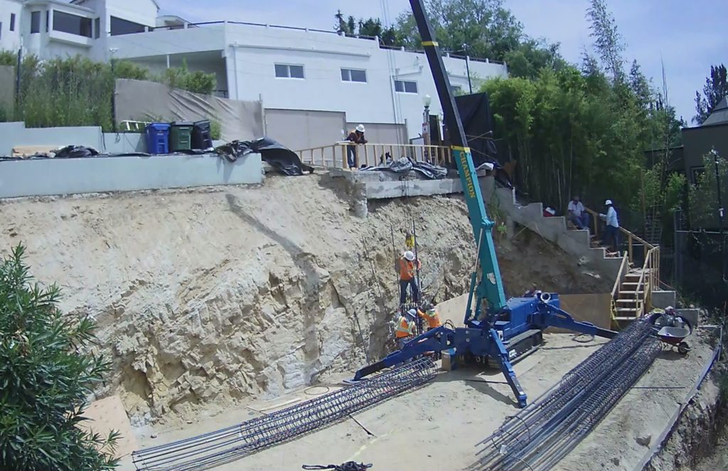
Excavated areas reached by the earthen ramp are sufficiently large in plan to set up cranes and install pre-assembled pile cages and grade beams. So, cages that can be transported to the site and delivered via Hargrave Drive and then transported up the ramp are assembled in the shop and installed with equipment. Cages in areas that cannot be reached from below are assembled on site and manually installed.
The large size and close spacing of reinforcing steel required by the City of Los Angeles Building Codes makes for densely installed steel in concrete grade beams and walls. Thus, in order to assure that concrete ties and other embedments can be installed in desired locations, steel reinforcing bars must be carefully laid out to avoid physical conflicts. Since the location of most vertical bars installed in walls are based upon bars installed in grade beams, the layout of bars in grade beams and other unexposed concrete pours is as important as in the exposed concrete elements.
The many multiple different sizes of bars, spacing, and structural overlaps in the various elements and within the same element makes it critical that fabrication and layouts are preplanned and documented and not just deciphered from the relatively generalized structural drawings as the installation proceeds.
Documentation
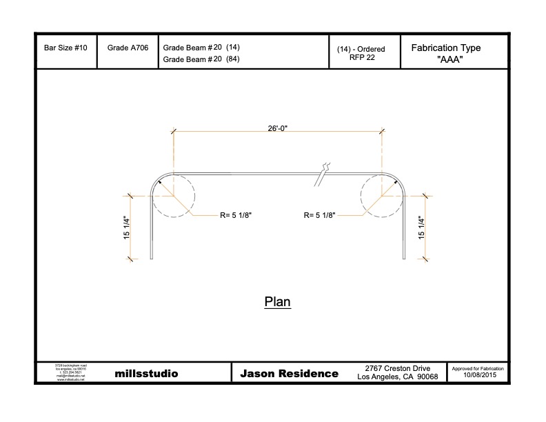
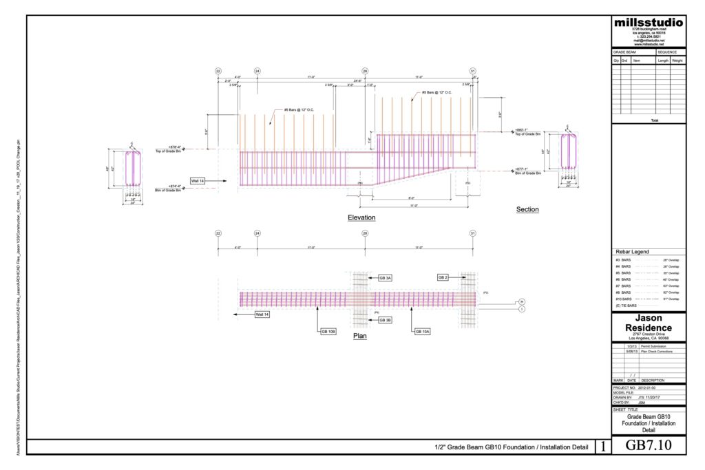
mills studio completed two categories of documentation specifically for the reinforcing steel: category one provides all details necessary to order and fabricate and category two provides all details necessary to assemble and place fabrications on site. These documents can be considered as Shop Drawings for Reinforcing Steel, but since mills studio is also the Contractor, the drawings are personalized knowing that they are for mills studio’s use and not a third party. For instance: drawings are color coded with different bar sizes shown with a different color that is consistent throughout all rebar drawings.
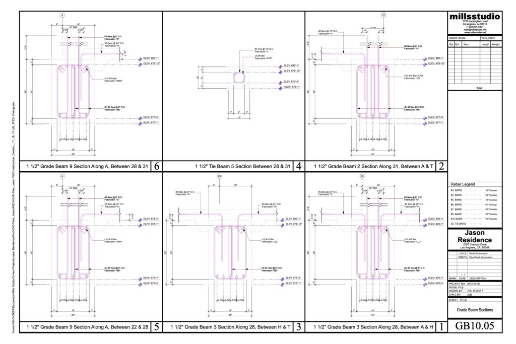
Each fabrication with any difference in bar size or configuration is provided with an individual letter designation and separate drawing with quantities designated for each separate pour sequence. Pile cage fabrication drawings include plans and elevations of each individual pile. Grade beam installation drawings are documented in plans for each of the four levels, plans and elevations of each individual grade beam, and sections and details applying to multiple grade beams.
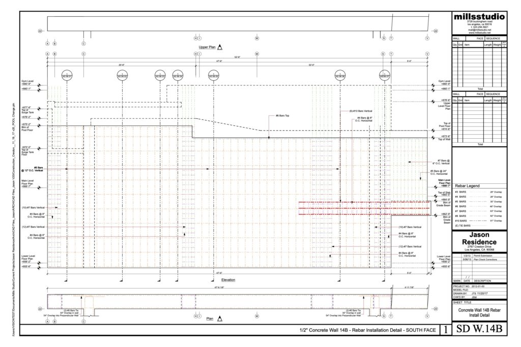
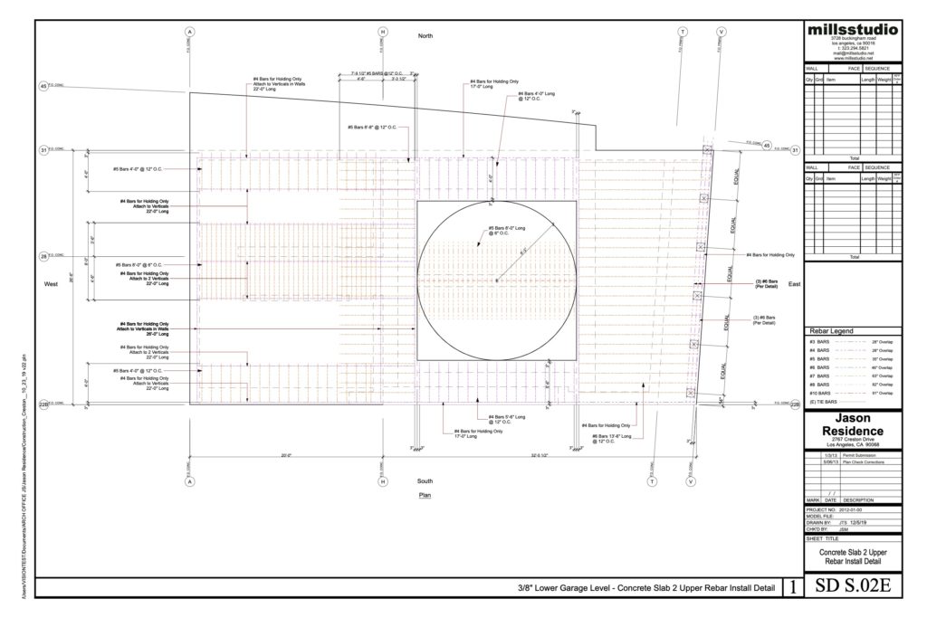
Each concrete wall drawing is shown in plan and elevation, with an elevation of each separate rebar curtain. Most all exposed walls contain two curtains with one on each face. These elevations show how subsequent concrete pours and other relevant building elements interface with each wall. Drawings for slabs show plans for each level of rebar in structural slabs and sections indicating the critical vertical spacing of bars. Most slabs require three individual levels of rebar. The motor court floating slabs with multiple levels and multiple beams contained in a single pour contain a number of plans and section details.